

UEFI rundown
The Extreme Tweaker (Ai Tweaker) section in the UEFI’s Advanced Mode is our area of focus for the final portion of this article. We’ll pick out functions of interest, or those that often raise questions, and provide some insight about what they do and when to use them. It’s a valuable resource if you’d like to improve your knowledge past the elementary levels. Don’t worry if it all doesn’t make sense, as not all of it needs to.
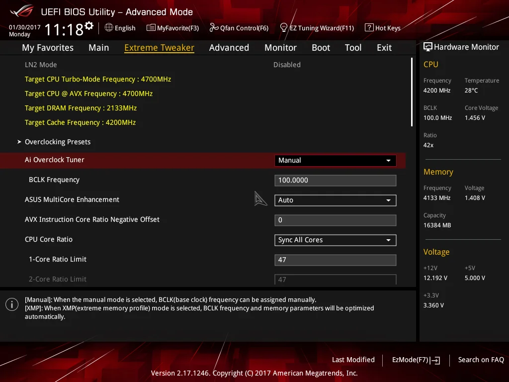
Ai Overclock Tuner: Set to Manual if you wish to adjust BCLK manually and other overclocking settings manually. Use the XMP setting to apply the Extreme Memory Profile of compatible memory modules.
BCLK Frequency: BCLK is the reference clock supplied to the CPU, Uncore, memory, PCIe, and DMI buses. Hence, any changes to BCLK will affect the operating frequency and stability of all associated domains. Ordinarily, changes to BCLK should not be required for a system that will be used as a workstation or gaming rig. The only exceptions to that rule are when a DRAM ratio that requires a different CPU strap needs a slight BCLK offset to obtain the correct memory frequency.
To take the hassle out of calculating frequency changes as a result of BCLK adjustments, the target frequency for the CPU, CPU AVX offset, DRAM, and Cache (Uncore) is automatically calculated and shown at the top left of the Ai Tweaker page.
ASUS Multicore Enhancement: Setting to Auto applies the Turbo ratio to all cores. Setting to Disabled uses Intel Turbo policies. These options are only effective at stock CPU settings. When a manual overclock is applied, the Turbo ratios are assigned according to the CPU Core Ratio settings.
AVX Instruction Core Ratio Negative Offset: This setting reduces CPU core frequencies by the applied value when an AVX workload is run. The thermal output of AVX workloads is an order of magnitude higher than for non-AVX workloads, which is why this setting has been introduced. By using this feature, we can utilize a higher operating frequency for light-load applications while heavy-load applications that contain AVX code will downclock the processor to help keep core temperatures below the throttling point.
CPU Core Ratio: There are two options for core ratio control:
Sync all cores: All core ratios will be set to the same value.
Per Core: Allows ratios to be applied to each core independently. In this scenario, when non-threaded applications are run, they can be assigned to cores that are running at a higher frequency to improve performance. However, current versions of the Windows operating system are configured to balance loads across all available cores, which results in all available cores reverting to the same ratio as the slowest core when faced with a workload. The workaround is to assign processor affinity for non-threaded workloads manually via the Windows Task Manager.
We recommend using the Sync All Cores setting in association with the AVX Instruction Core ratio Negative Offset setting, or with the ASUS CPU overclocking temperature control features to get the best performance from the Kaby Lake architecture.
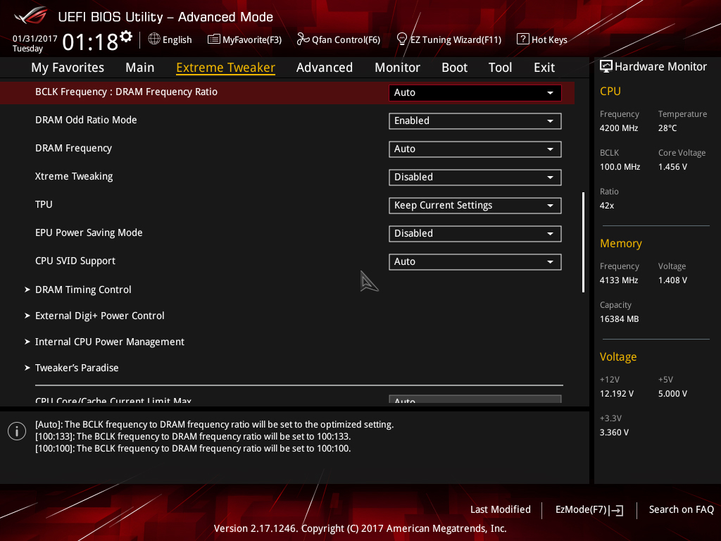
BCLK Frequency: DRAM Frequency Ratio: Sets the ratio of DRAM frequency to BCLK. For normal use, this setting can be left on Auto, as it will choose the best ratio according to the user-selected DRAM Frequency.
DRAM Odd Ratio Mode: When enabled, all DRAM ratios are made available – spaced at 100MHz and 133MHz intervals all the way to the functional DDR4-4133 ratio.
DRAM Frequency: Allows you to select the memory operating frequency. When XMP is configured, the correct frequency for the memory kit is selected automatically. The DRAM ratio option only needs to be set if you intend on setting the memory speed manually for overclocking purposes.
Note that the highest working memory ratio is DDR4-4133. Higher speeds require usage of BCLK with the DDR4-4133 (or a lower) memory ratio selected.
Xtreme Tweaking: When enabled, provides a score boost in very old legacy benchmarks such as 3D Mark 01. It has no impact on performance for other applications so can be left disabled.
CPU SVID Support: Can be left on Auto for all normal overclocking. SVID allows the processor to communicate with the CPU Core Voltage power delivery circuit in order to change voltage on-the-fly for power saving purposes and allows power levels to be read by monitoring software. For Adaptive and Offset Mode for CPU Core/Cache Voltage, this setting must be set to Auto or Enabled. For all normal overclocking a setting of Auto can be used without requiring adjustment.
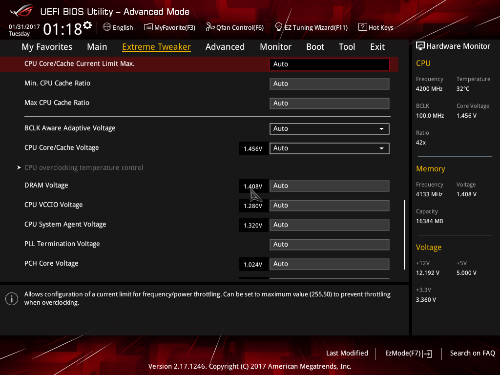
CPU Core/Cache Current Limit Max: Allows setting a current limit for frequency/power throttling. Can be left on Auto for all normal overclocking purposes to prevent inadvertent throttling when the CPU is under load.
Min. CPU Cache Ratio: Defines the minimum Uncore ratio when enters CPU power saving state. Can be left on Auto for all normal use unless you wish to experiment with a different minimum value. To prevent downclocking of the Uncore domain, set the minimum ratio to the same value as the maximum ratio.
Max CPU Cache Ratio: Defines the maximum Uncore ratio when the CPU enters load state. For overclocking purposes keeping the maximum value within 3 ratios (lower) of the applied CPU Core ratio is sufficient for performance. Note that changes to the maximum ratio should not be experimented with until stability has been established for the CPU cores and memory (DRAM).
CPU Core/Cache Voltage: Sets the voltage control mode for CPU Vcore and the Uncore:
Manual Mode: Allows setting of a single value for Vcore that is applied across all Core ratios, irrespective of application load.
Offset Mode: In Offset Mode, we can add or subtract voltage from the CPU’s default voltage for a given CPU core ratio. The default voltage scales according to the active multiplier ratio. This provides power saving when application loading is light. The side effect to using offset mode is that any offset value we select will be applied to all core ratios. This can result in too much or too little voltage being applied for a given ratio, which leads to instability.
If you wish to use Offset Mode, then bear in mind that the Vcore displayed in the UEFI is simply a snapshot of the offset voltage stack; the firmware interface only places a partial load on the CPU. The full-load voltage in the operating system will be different, so you will need to check the voltage by running a suitable application within the OS. Use Ai Suite to monitor the voltage when the system is under full load. Also, bear in mind that the default voltage receiving the offset changes with the applied CPU ratio.
Adaptive Mode: Adaptive Mode was developed to account for the inadequacies of Offset Mode for overclocking. We use it to specify the voltage used when the CPU is faced with a heavy application load. The voltage we set is the maximum voltage the PCU is allowed to apply, which takes all the load-related guesswork hampering Offset Mode out of the equation. The other boon of Adaptive Mode is that it does not alter voltages for non-Turbo CPU ratios, allowing us to enjoy the benefits of power saving without the voltage adjustment range issues presented by the Offset Mode function. We recommend Adaptive Mode for all normal overclocking.
To use Adaptive Mode, simply enter the full load voltage you wish to use in the Additional Turbo Mode CPU Core Voltage box. So, if you wish to set 1.20V for full load, just type 1.20 into the box. The target full-load voltage is shown in the Total Adaptive Mode CPU Core Voltage area.
When using Adaptive Mode, configure the following settings within the Internal CPU Power Management sub-section:
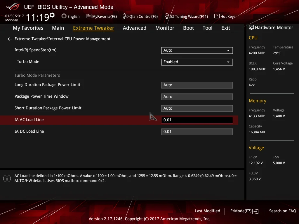
- Set IA AC Load Line to 0.01
- Set IA DC Load Line to 0.01
- Press the escape key on your keyboard to return to the previous page
Setting these values keeps the Adaptive Mode voltage closer to the user-applied value when the processor is under full load.
Note that the Adaptive voltage target works on the Turbo ratios only. So, if you use a non-Turbo CPU ratio, the value in the Adaptive voltage setting box will not be applied. In such instances, use Offset Mode or Manual Mode for CPU Core/Cache Voltage.
The major caveat of Adaptive Mode is that the minimum possible voltage for a given ratio is pre-programmed into the CPU. If you happen to have a very good CPU that can run at a lower voltage than the minimum adaptive voltage for a given ratio, there are only two ways to lower the value. The first method is to apply an offset. That’s why there is the option to apply an offset when in Adaptive mode. The offset value is added or subtracted from the Additional Turbo Mode CPU Core Voltage box, and the total is displayed in the Total Adaptive Mode CPU Core Voltage pane. The side effect of applying an offset is that it affects the entire voltage stack – from idle to Turbo ratios, which can limit the usable offset voltage range.The second method is to use the CPU Load-line Calibration setting in the External DIGI+ Power Control section. Using a lower value will lead to more sag under load, resulting in a lower voltage. Again, the issue with this is that it will affect how much voltage the CPU receives under all loading conditions, which can lead to instability when it is too low for a given load state, or when the CPU transitions from idle to load state.
Even with those caveats, we still recommend using Adaptive Mode for all normal overclocking, unless your processor can run at voltage levels that fall substantially below the minimum adaptive voltage for the applied CPU core ratio.
DRAM Voltage: Sets the memory voltage (VDIMM) for the memory modules. When XMP is applied for the memory kit, the correct voltage will automatically be configured. Adjustments are only necessary if your memory kit does not support XMP (unlikely), or if the memory is proving unstable after making adjustments to System Agent voltage, VCCIO, and memory timings.
CPU VCCIO Voltage: This rail is for the IO transceivers within the CPU. Its primary impact is on memory stability, although, it usually does not need to be increased as much as the System Agent voltage. Keeping this rail within ~0.05V (lower) of the System Agent voltage is often sufficient to stabilize memory frequency.
When making adjustments to this rail, bear in mind that applying too much voltage can lead to instability. Make adjustments gradually.
CPU System Agent: The System Agent is responsible for handling IO between the CPU and other domains. From an overclocking perspective, the System Agent voltage is especially important for memory overclocking.
For memory speeds over DDR4-3600 or if using high-density memory kits, voltages up to 1.35V may be required. Some CPUs have “weak” memory controllers that require elevated voltages to maintain stability. If possible, do not venture too far from 1.35V as a maximum.
The System Agent voltage can induce instability if set too high, so it is wise to make gradual changes rather than applying arbitrary values and hoping for the best.
PLL Termination Voltage: Leave this at Auto; adjustment of this voltage is only beneficial for extreme overclocking with sub-zero CPU cooling.
PCH Core Voltage: This is the core voltage supply for the PCH (platform controller hub). This setting should not need adjustment for most overclocking.
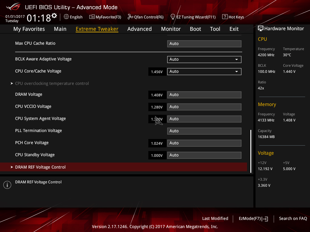
CPU Standby Voltage: Leave at Auto for all normal overclocking. Adjustment of this rail is only required for extreme overclocking with sub-zero cooling.
That concludes the Kaby Lake overclocking guide. We look forwards to your results! Please post any questions in the ROG Forums.