[tabgroup]
[tab title=”Introduction”]
Thinking of building your first PC? If you’ve chosen to custom build a system, chances are that you’ve got specific needs, looking to save money or simply because you enjoy DIY. In order to make your first PC building experience a memorable one (for the right reasons), there’s a plethora of things you’ll need to learn; picking parts, software options, the mechanical elements of putting everything together, and also configuring the system.
Don’t let that put you off. Once you’ve done it, there’s no turning back. You’ll be able to upgrade parts, build PCs for others and get what you need from the system rather than having to make do with someone else’s choices. Whether you’re looking for the best performance, or if you’re saving money, going the DIY route puts you in control. It allows you to balance parts choices according to budget, often providing a better all-round user experience than buying pre-built.
Searching the internet and posting questions on user forums can help you pick the right parts and help with software configuration, however, there aren’t many, if any guides that cover the mechanical elements of putting a PC together.
Having conversed with and helped end-users for a number of years on public forums, I’ve dealt with first-time builders who ask for help as a last resort. Often, a lack of understanding leads to mishap or outright frustration during the building process. Some of these issues can be solved by telling the user which page of the motherboard manual they need to read (hint for the fly-by-the-seat-of –your-pants types among you). Others require different parts, and in the worst cases I’ve encountered, misadventure leads to components dying.
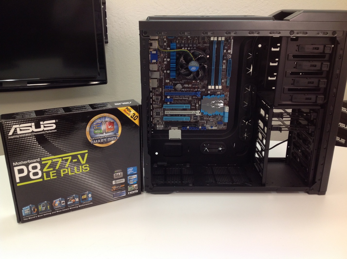
Perhaps things would be easier if there were more beginner-oriented guides on the internet, so we’ve put together a PC building guide based around the ASUS P8Z77-V LE Plus motherboard. We’ve included step-by-step pictures, showing the order in which we put our systems together. There’s also a few web links to helpful videos which focus on various parts of the build process. To make it easier still, we’ve listed all the parts used so you can build something similar – cutting out a lot of additional research work for you.
[/tab]
[tab title=”The Parts”]
The focus of this article is on the build itself, so we won’t go into excruciating detail on the parts used. However, we’ve provided a list below together with a brief overview of some of our choices.
[qd_table]
| Motherboard: P8Z77-V LE PLUS | CPU: Intel Core i5 3570K |
| Memory: Corsair – Vengeance 1600 8GB kit | Optical drive: ASUS BC-12B1ST |
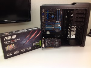
| Graphics: ASUS Direct CU II GTX 650 Ti BOOST | Chassis: Corsair Carbide 400R |
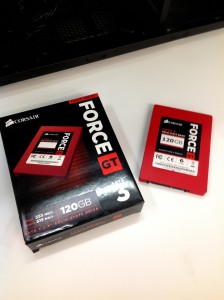
| PSU: Corsair Professional Series™ Gold AX650 | SSD: 120GB ForceGT or 240GB NeutonGTX |
| OPTIONAL | |
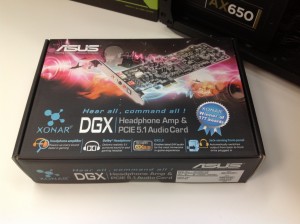
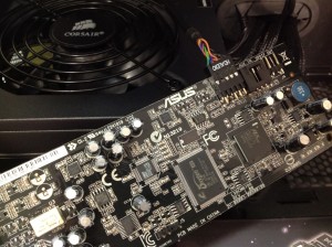
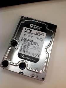
| 1TB or 2TB HDD | ASUS Xonar DGX Audio Card |
[/qd_table]
Our goal was to put together a snappy and multi-functional system, capable of being used for gaming/HTPC/workstation – within a $1000 budget. We’ve used a selection of entry-level to mid-range parts; picking those that provide low-noise while providing excellent performance and reliability.
If you’re working on a tighter budget, there’s money to be saved by opting for a cheaper chassis (Corsair 200R) and using the on-board sound instead of using the Xonar DG soundcard. Should budget be a big concern, then the processor, graphics card and SSDs would be areas where savings can be made, at the obvious expense of performance.
The P8Z77V LE Motherboard
The P877V LE is a full sized ATX motherboard provides the perfect foundation for a first time PC build:
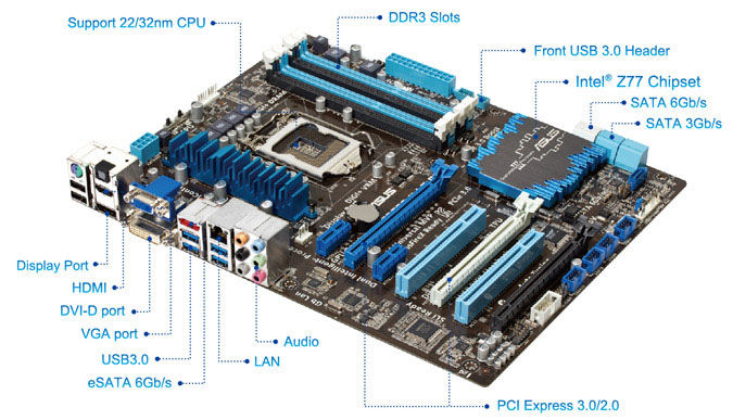
Check out the product page here for a lowdown on the features. A few of the things that set this board apart at the price are the fan controls and its UEFI interface. Fan controls are often overlooked by first- time builders. Without having control over how fast the fans spin at a given temperature, there’s a chance that you’ll end up with a PC that is unnecessarily noisy. Having the ability to set various speed and temperature policies easily, helps keep fans spinning at optimum levels for the workload placed on the PC. The fans will ramp up to a high speed when you’re gaming or encoding a movie, and then spin at whisper-quiet levels when browsing the internet or watching a movie for example.
Then there’s UEFI, which stands for User Extensible Firmware Interface. Basically, UEFI is a graphical user interface that was as users need to setup our motherboard and how it interacts with various components. Setting the priority of attached drives, configuring fan speeds and manual overclocking are just three of the things you need to use UEFI for. ASUS motherboards are recognized as having the best UEFI implementation – it’s well laid out and easy to use.
Bundled with the motherboard, you’ll also get a comprehensive set of software tools that can be installed into the operating system. Automated overclocking (providing a “free” speed boost to the system), fan speed profiles and easy ways to update the system drivers/UEFI are a few of the features touted by ASUS’ AI Suite software. Those are just a few of the things that will make system setup and tuning easier for you.
ASUS Direct CU II GTX 650 Ti BOOST
If you are looking for a 2-slot graphics card that’s capable of driving high resolutions on the latest games or editing programs without breaking the bank, the ASUS GTX 650 Ti BOOST is a great card for under $175.00. Not only has ASUS overclocked the base clock of the reference to 1020MHz, NVIDIA’s GPU BOOST technology pushes it even further to 1085MHz, allowing you to play your games at higher frame-rates.
ASUS’ Direct CU II cooler, provides 20% better cooling than the reference cooler by using copper pipes and two 80mm fans to push the air. The GTX 650 Ti BOOST is PCIe 3.0 compatible and has 2GB GDDR5 memory. Included with the graphics card you get ASUS GPU Tweak, allowing you to tune your GPU in real-time right from your desktop. Learn more here: (http://youtu.be/zkJez9Og7fc)
[/tab]
[tab title=”The Build Stage 1″]
Stage One
[toggle title=”Toggle title”][/toggle] Start by installing the CPU into the motherboard. The motherboard manual comes with instructions of how the CPU should be installed. Chapter two of the ASUS motherboard manual covers board layout and component installation procedures in detail: [VIEW HERE]
If you’re using an after-market cooler that has a back-plate, you’ll need to get that installed before you proceed to installation of the motherboard in the PC case. Follow the instruction set that comes with the cooler to the letter.
Take both side-panels off the case and check the PC case motherboard tray standoffs are in the correct location for the motherboard. There should be one standoff for each hole. Should a standoff not align with any of the holes, remove it, or move it to the correct location. A stand-off placed in the wrong location may cause a short against the back of the motherboard which will kill components.
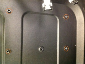
Under no circumstances should a motherboard be installed directly against a motherboard tray, this will kill the motherboard and possibly your expensive components. Believe it or not, I saw a post online recently where a user made this mistake – the outcome was not a good one. The P8Z77V LE has nine mounting holes, so you’ll need nine stand-offs. You can remove any extras from the chassis by unscrewing them. Make sure the stand-offs are in the corresponding locations in the tray for the holes in the board.
Next, install the rear IO/shield supplied with the board into the correct position at the rear of the case. It should “click” into place.
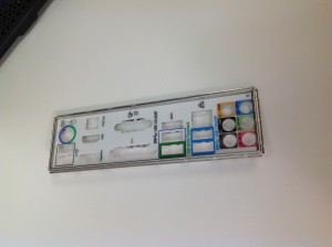
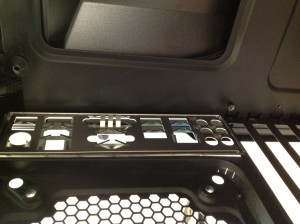
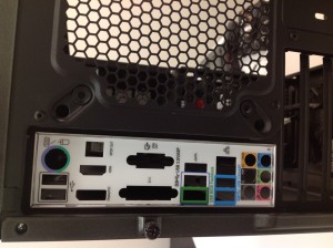
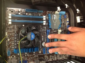
Lay the chassis on its side and then manoeuvre the motherboard into position and start inserting and tightening screws. There are 9 screws in total for the P8Z77V-LE, see the picture below for locations:
[/tab]
[tab title=”The Build Stage 2″]
The Other Components
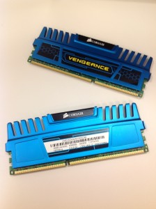
Memory Modules
At this point, you’ve got a choice of inserting the graphics card or memory modules. Although we went with the graphics card first for our build, we’ll show you the memory modules first because some motherboards are space restricted and it can be easier seating the memory first.
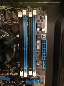
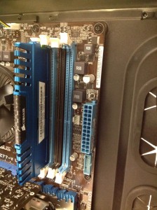
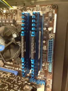
We’re using two modules for this build. On many platforms the secondary memory slots are best occupied first. This is due to how the signal lines are routed from the memory controller to the slots and also a requirement on some platforms which won’t POST unless the secondary slots are populated first. On our P8Z77V-LE those are the blue slots:
Graphics Card
It’s time to install the graphics card:
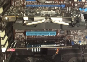
You’ll want to lay the chassis on its side to install the GPU – it’s a lot easier that way. Typically, the GPU will occupy the primary PCIe full length slot, closest to the CPU. That’s because most of the PCIe traces on the motherboard are routed to the first full length 16X slot first and it can operate at full 16x width if no other slot on the PCIe bus is occupied. If you insert the card into a lower slot, then the card operates at 8X or 4X depending upon the slot used. That’s the main reason the top-most 16X slot is used for single graphics card systems. On the P877V LE, that’s the dark blue slot with the butterfly latch.
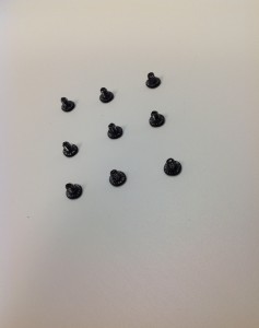
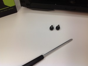
We need our screwdriver once again and a couple of thumbscrews:
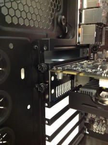
“Open” the butterfly latch on the dark blue PCIe slot. Don’t push it back too far or it’ll break. Insert the graphics card into the slot. It’ll only go in one way and you’ll see the latch close when it’s seated firmly in the slot. Don’t use excessive force!
With the graphics card seated, you’ll need to secure it with those thumbscrews we showed you earlier.
We can repeat the process for the Xonar DGX soundcard which fits into the black PCI slot at the bottom side of the board. You’ll only need a single thumbscrew to secure it.
The Power Supply Unit
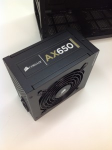
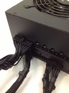
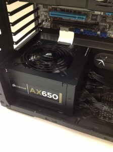
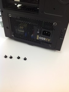
With the graphics and sound card in place we can move on to installing the PSU in the chassis. We’ve chosen Corsair’s venerable AX650 for our build. It’s suitably specified and efficient. What’s more, it’s a modular design which means you only need to insert the cables you need. This allows for a tidy build as opposed to non-modular PSUs where all additional cables cannot be removed and take up space inside your case, restricting airflow and looking messy.
You’ll need the ATX 12V, EPS 12V, PCIe and SATA and possibly Molex cable looms as standard for most installations. Adjust the number of SATA or Molex connectors you need for your build to suit.
Follow the instruction set that comes with the AX650. Be sure to seat each cable firmly so that the connector latches into place.
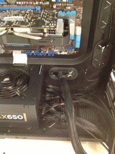
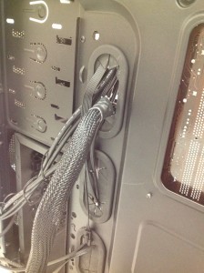
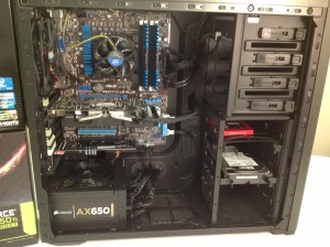
With the PSU secured in place, we can start routing the cables. You’ll see why we’ve opted for the Corsair chassis below:
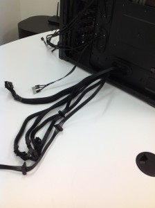
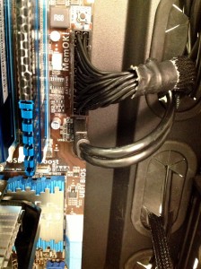
Feed all the power cables through the available holes. Use a hole near to the connector the cable will be seated in. ATX 12V, PCIe and EPS 12V connectors should all be inserted into the relevant locations at this stage, with any slack in cable length tucked at the back of the motherboard tray to keep the motherboard side free from clutter.
Quick PSU Cabling Time Out
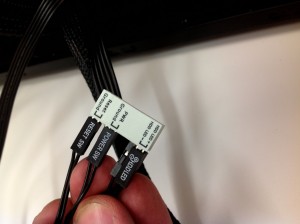
Interlude. While we’re finding those PSU cables a final home, there’s also the pesky front panel cabling to take care of. The case will have cables for power and reset switches, together with LED activity indicators. To make things easier, the ASUS P8Z77V-LE ships with a “Q-Connector”. It’s silkscreened to highlight where each of the front panel connectors go. Be sure to keep the LED connectors with writing facing outwards for correct polarity. Otherwise, the LEDs won’t work.
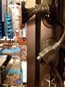
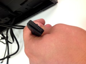
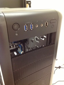
We also need to take care of the other front panel connectors – the Corsair chassis comes with front panel USB 3.0 ports. Locate the cable and route it through the case to fit snugly into the onboard USB 3.0 header.
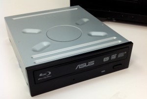
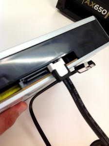
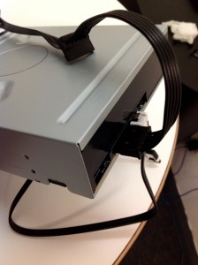
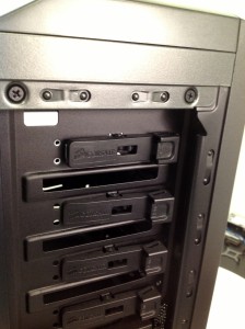
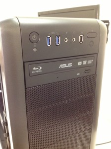
Now’s a good time to install our blu-ray drive:
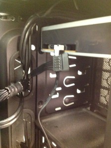
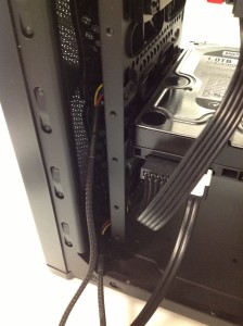
Slide the drive into the bay, and attach the SATA data and power cables as shown below:
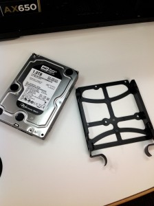
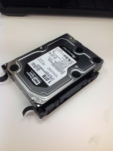
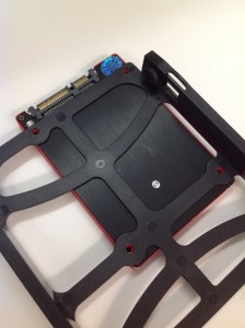
Let’s get some power and SATA cables plugged into the drives so the motherboard can communicate with them…
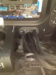
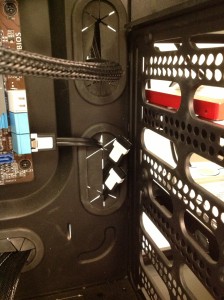
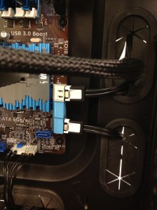
Once again route the SATA data cables via the rear of the case and then through the cabling hole near the motherboard SATA ports:
Take a breather at this point. After that, you can proceed to connect up your monitor, keyboard and mouse to the PC and power the system up for the first time. Assuming all is well, you should be greeted by a POST screen. From there you can start configuring the system and installing software. If you’re in need of a guide for that part of the build, look out for a future article detailing software setup tips on ASUS motherboards.
[/tab]
[/tabgroup]

