The launch of ASUS Z87 Motherboards has given end users many decisions to make. For those that decide to build a new PC – whether or not they’ve built before – getting the best motherboard for your dollar can be tricky.
With more circuitry on the processor die than the previous generation CPUs, a number of power supply decisions are easier for the motherboard engineers since Haswell reduces the amount of independent power supplies provided to the processor. Haswell contains its own power circuitry on-die, generating several internal supplies from a separate external power supply.
However, with this in mind, motherboard selection and quality should still be at the forefront of your decision-making. UEFI functionality, bundled software, the number of fan headers (and the ability to control them), motherboard layout, parts validation, warranty and customer support are just a few of the things that differentiate motherboard vendors. They are things that shouldn’t be taken lightly, and you should spend the time to familiarize yourself with them all before making a motherboard purchase. Doubly the case if this is your first ever DIY PC building experience as it may end up being your last if things do not go smoothly.
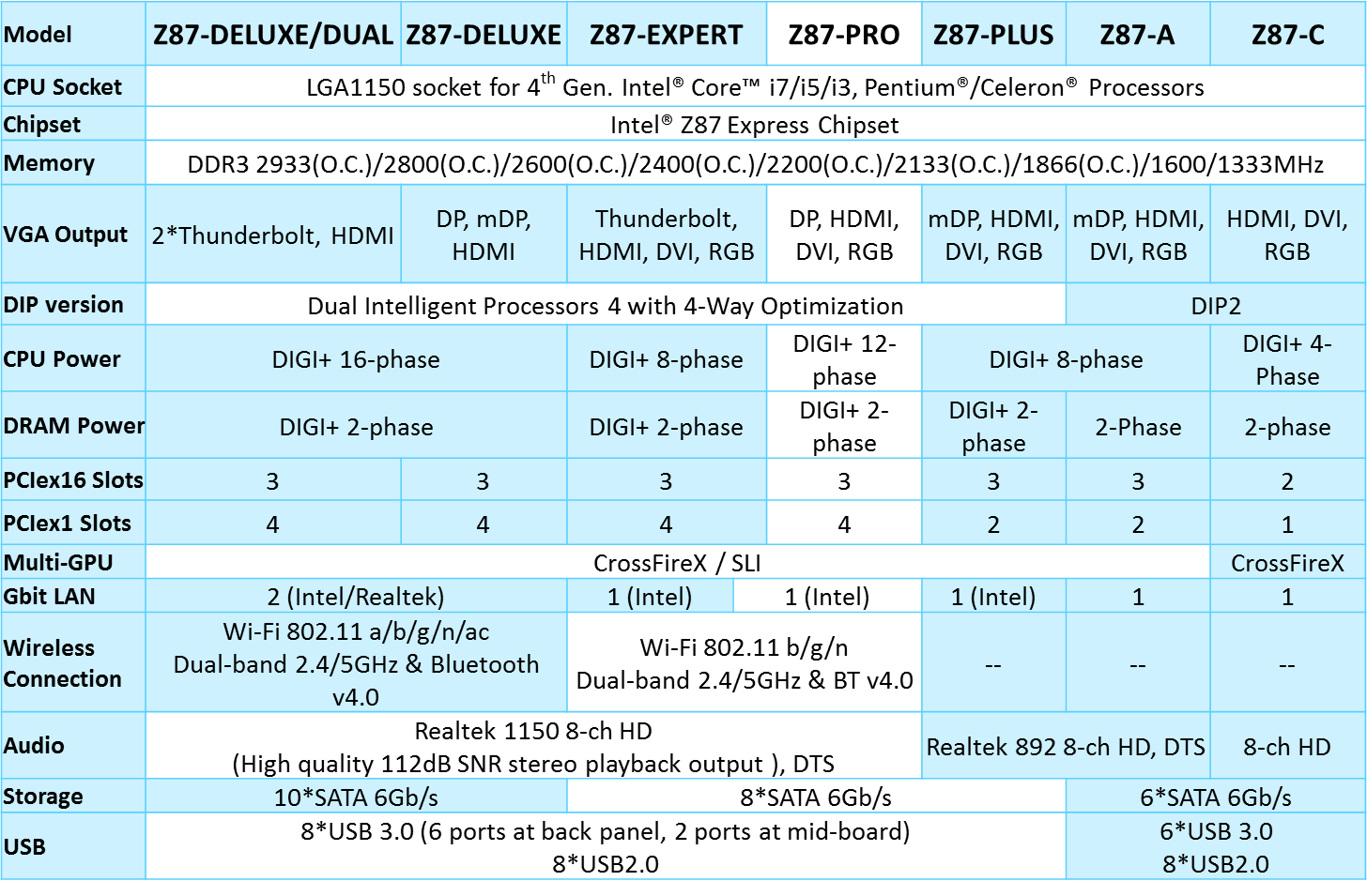
At ASUS, we’ve developed separate motherboard categories for different usage scenarios. There are mainstream, gaming, workstation and enthusiast oriented segments. A quick head count of ASUS Z87 motherboards gets us close to twenty models – that is a lot of products to choose from at launch. If you are wondering what sets some of them apart, fear not, over the next few weeks, we’ll be posting up build guides and videos centred on a number of these motherboards that will help you choose the right one.
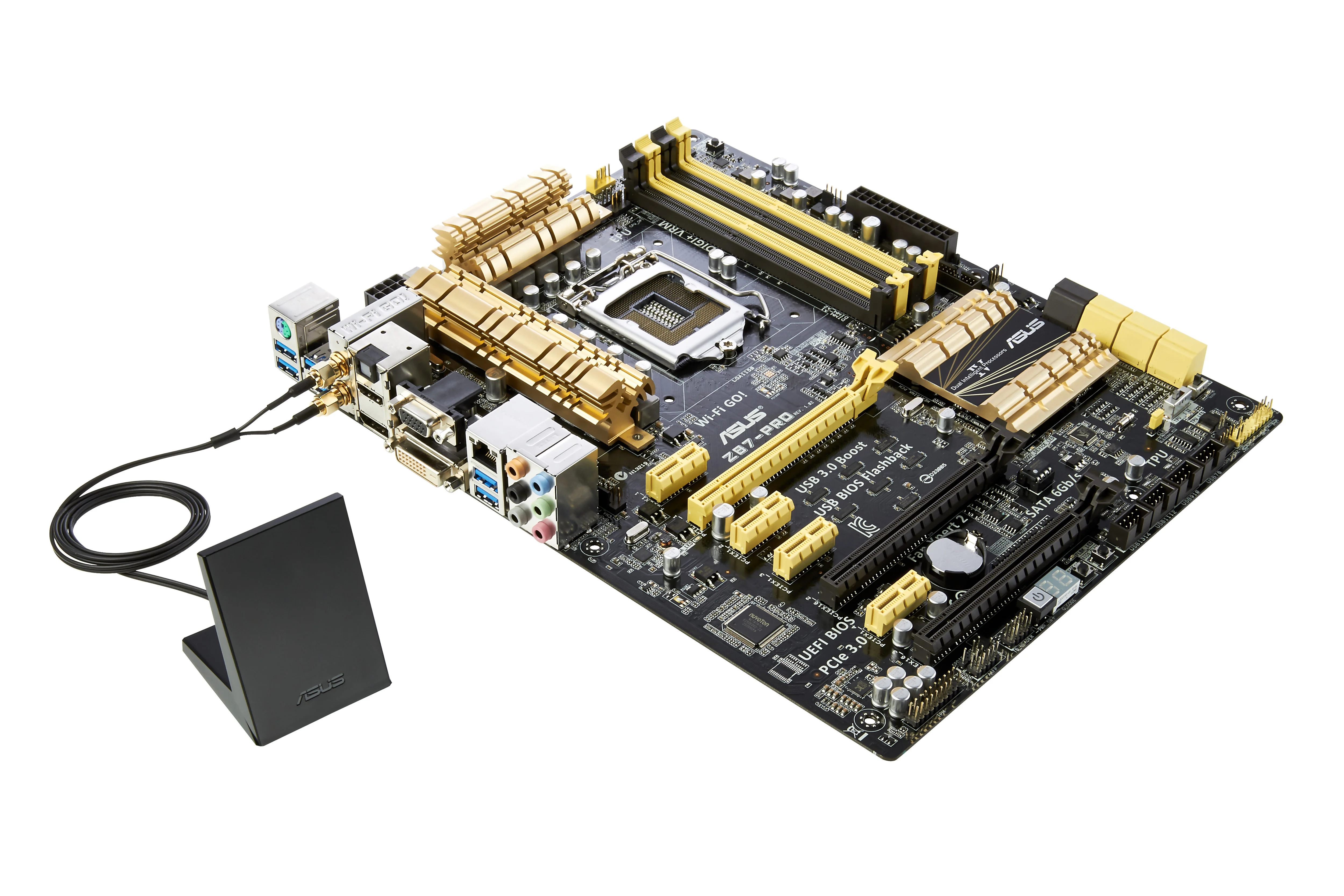
To kick off ASUS’ coverage here at PCDIY today, we’ve taken one motherboard from the mainstream line-up and aim to provide an overview of its features. The motherboard we’ve chosen is the ASUS Z87-Pro. Priced at $209.99 it sits squarely in the center of the mainstream product stack.
The Z87-Pro sits at a point where we have an outstanding balance of features for the price – with integrated peripherals and software features that make for a multi-functional PC.
Let’s start making sense of some of the features this board offers…
Hardware Features of the ASUS Z87-Pro
Intel I217V LAN
The Z87-Pro includes Intel’s latest I217V Ethernet controller. The I217V offers improved processor off-loading while consuming 90% lower power than Intel’s previous generation controllers.
Processor off-loading refers to how much load the LAN places on a CPU. During periods of heavy activity when the CPU is dealing with requests from other parts of the system, networking throughput can suffer if the Ethernet controller is not capable of dealing with most of the load itself. In an online multiplayer game, this could manifest as glitching which would ruin gaming experience. A robust network controller will not require the CPU to handle most of the network related load, freeing up the CPU for other tasks, and that is where the I217V shines.
802.11n Dual Band Wi-Fi
The Z87-Pro features a Wi-Fi daughter-board that supports dual-band 802.11n transmission protocols. The Wi-Fi daughterboard is conveniently placed within the rear IO cluster – which avoids sacrificing a PCIe slot and keeps it away from areas of high heat (near graphics cards for example).
We have revised the design of the Wi-Fi antenna. The new design incorporates two antennae within a single unit. It is now easier to locate and direct the antenna towards the router. The module connectors have also been upgraded to solid SMA fittings – which are more reliable than clip-on types. Plus the antennae easily be replaced with readily available SMA based offerings. Lastly, the base of the antenna is magnetic and will easily attach to the side of a steel chassis for convenience.
Optional Extra – NFC Express
Bundled with the Z87-DELUXE/Dual and available as a separate accessory for ASUS 87 motherboards, NFC Express brings a new way to interact with your PC using either your NFC-enabled Smart devices or the included tags. By scanning your Smart Device or tag on the NFC Express module, the user can perform a variety of actions, from logging in and launching programs to transferring files, all with the simple wave of your Android-based Smart Device** or tag. In addition, though the NFC Express requires one USB 3.0 port, it provides two additional USB 3.0 ports in return, increasing versatility and usefulness of an already intuitive design.
Near-field communication (NFC) technology works by inductive coupling. The magnetic field of two NFC capable devices reacts when they are in close proximity to one another (within 5 centimetres). These changes in magnetic field are converted into pulses and then decoded to complete the NFC data exchange.
Ai Suite 3 Software Features
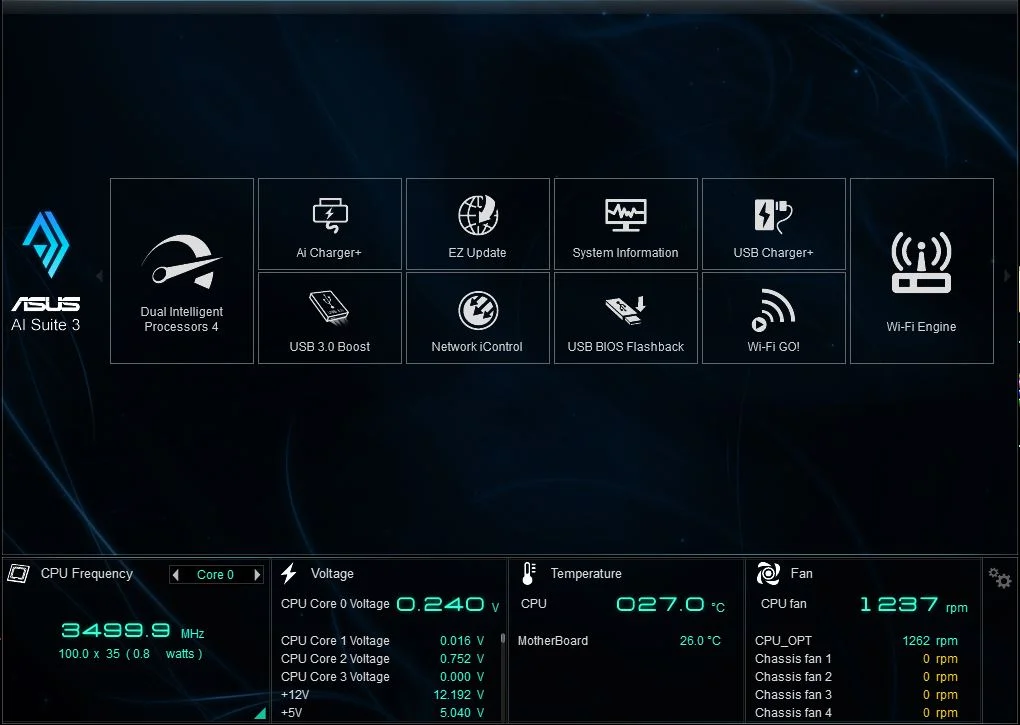
The latest iteration of ASUS’s motherboard related software suite is Ai Suite 3. This fully integrated software package provides a simple and intuitive way of setting up advanced features and tuning the system for optimal performance.
CPU Frequency, system voltages, temperature and fan speeds are all displayed persistently within the lower portion of the Ai Suite 3 user interface. Above them icons representing the 10 modules available for the Z87-Pro can be accessed by clicking on them.
The 10 modules are:
- Dual Intelligent Processors 4 (4-Way Optimization)
- Ai Charger+
- USB Charger+
- USB 3.0 Boost
- EZ Update
- Network iControl
- System Information
- USB BIOS Flashback
- Wi-Fi Go!
- Wi-Fi Engine
The installer for Ai Suite 3 allows selection of modules to install – any modules that you don’t want can be de-selected in the installation options page.
Some of the most useful functions of Ai Suite 3 are detailed below:
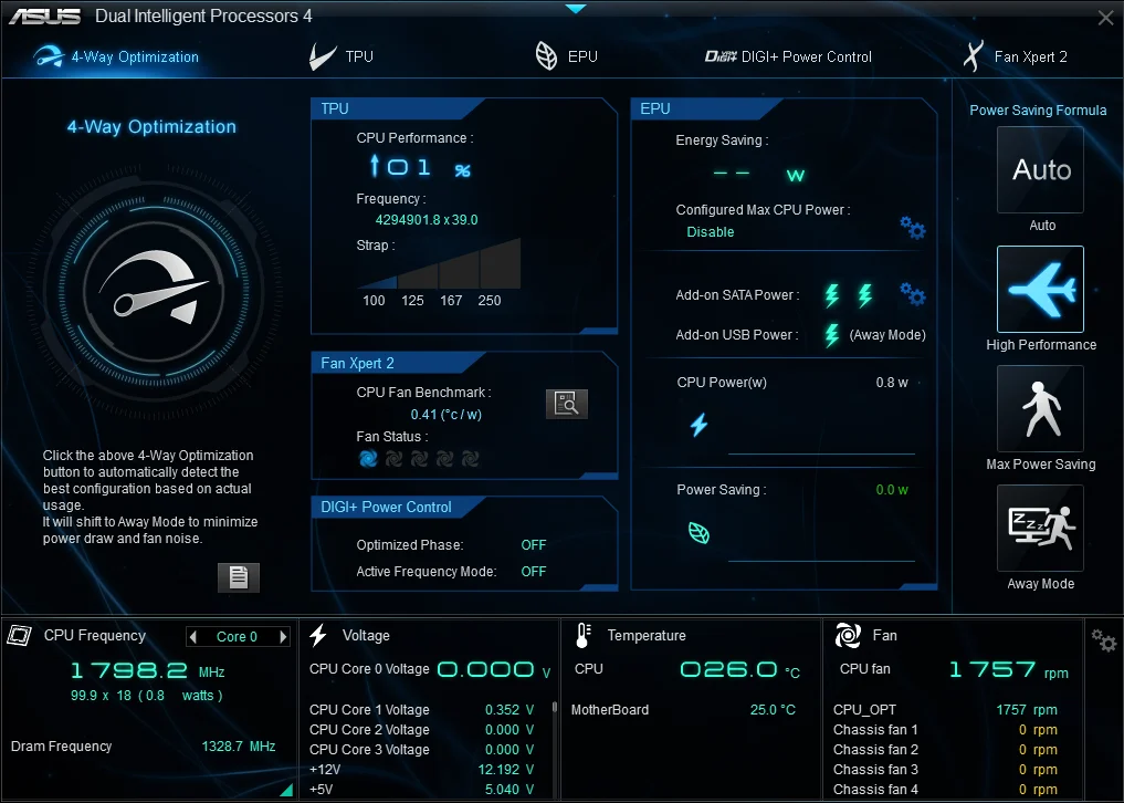
4-Way Optimization
The four facets of 4-way Optimization are Auto Tuning, EPU, DIGI+ Power and Fan Xpert II. A single click of the 4-way optimization button will optimize the system 4 ways (as the name implies).
If all four modules are user selected, the whole process takes about 10 minutes to complete and is capable of providing a CPU overclock to around 95% of its frequency potential in comparison to manually tuning the system.
The overclocking portion of the test runs a Prime derivative stress test. First, the software increases the multiplier ratio of two cores, and if they pass the test, then the remaining two cores ramp to the same frequency and the test repeats. The process continues until a detected failure, at which point the system clocks return to the last multiplier ratio that passed. Allowing the software to ramp the core multiplier ratio in pairs takes maximum advantage of system cooling. If two cores are stable at 4.7 GHz, but four cores are not, then the final overclock may end up running two cores at 4.7GHz while a four core load will operate at 4.6GHz.
The system is then optimized for power savings at idle-light loads by the EPU optimization procedure. Next, power delivery settings are increased by DIGI+ while all attached fans are calibrated by Fan Xpert 2 to ensure optimal speeds and noise levels in relation to system loads.
Individual modules of the 4-way process can be configured individually or manually if you prefer. And as pointed out earlier, there is the option to prioritize multiplier overclocking over BCLK overclocking (multiplier overclocking is default).
Auto-tuning writes overclocking settings back to UEFI. For those that prefer manually tuning a system, running 4-way optimization first is an excellent starting point. More so the case when unfamiliar with a platform and which parameters to adjust. The software can be used to arrive at a stable system overclock, and then adjustments made in UEFI based on preferences.
Energy Processing Unit (EPU)
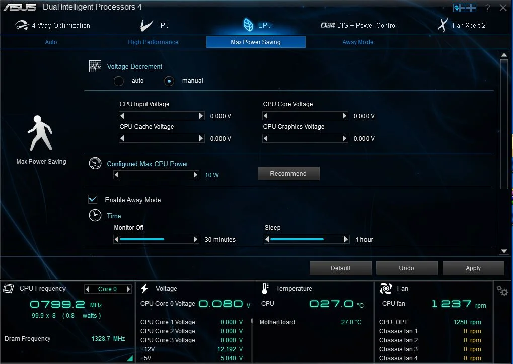
As previously mentioned, there are four separate modules that generate the 4-way optimization process. These modules can be configured individually and manually if you wish. We won’t delve too much into the manual options within in this article as some are designed for advanced users. However, there is a feature in the EPU module that’s worth mentioning.
The slider named “Configured Max CPU Power” allows users to specify a maximum power threshold for the processor in Watts. The way this works is by lowering the processor’s core speed to a level that ensure its power consumption will not breach the defined value. It’s convenient for configuring a low power system which does not require a high CPU frequency for superior performance – such as a file server or watching video content.
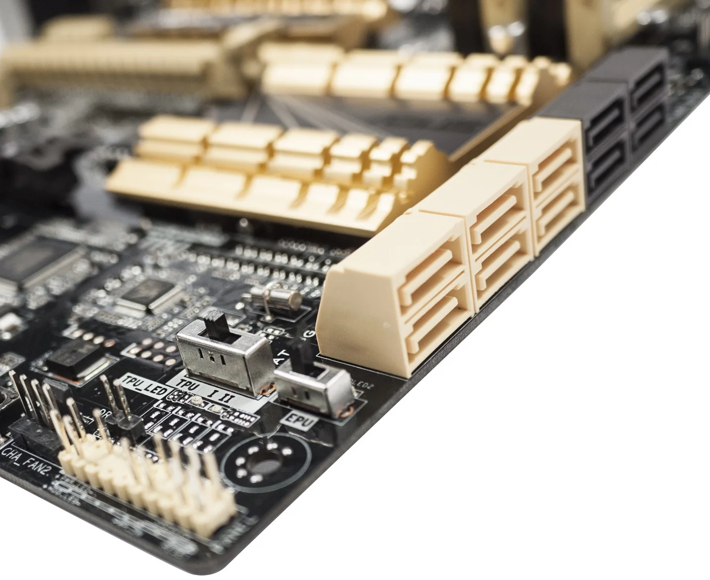
EPU and TPU Switches
EPU and TPU switches are placed on the motherboard that negate the need to use Ai Suite 3 or the UEFI if you prefer a direct process.
Simply slide the required switch while the system is powered off, then power the system on and let the EPU/TPU microcontrollers take care of the rest.
While using the hardware switches isn’t as flexible as using 4-way optimization in Ai Suite 3, we’ve made some subtle improvements to TPU to adjust the thermal aspects of Haswell processors. TPU has two stages; moving the slider to position one will over clock two cores to 4.3GHz, one core to 4.2GHz and the last core to 4.1GHz. If all four cores are loaded, the core frequency will cap at 4.1GHz. Setting the TPU slider to this position will automatically apply the XMP profile for memory, so there is no need to enter UEFI to do so! This profile has been designed with the stock Intel cooler in mind or entry level after market cooling. Using position number two results in a 4.25GHz overclock on all four cores. This profile is suitable for most aftermarket coolers.
Fan Expert II
PCs are full of components that produce heat. Graphics cards, the CPU, memory, power supplies, on-board controllers, are all contributors. Components that offer higher levels of performance usually have a side-effect of running hotter. This heat needs to be removed from the PC case and that’s why fans are a necessity for most personal computers.
Fans for computers come in various guises, from high-speed or general use to those geared for low noise. Low noise fans don’t shift a lot of air. They’re only suitable if the components used within the PC don’t produce a lot of heat. The thermal efficiency of the PC case used plays a part in fan choice as well – ventilation and airflow needs to be good for a PC case to be suitable for quiet fans. Most PC cases come pre-fitted with fans that are reasonably quiet at low speed and moderately loud at high speed in order make them suitable for general PC use.
Depending upon how much the PC case costs, a crude level of manual fan control may be built-in. A three stage slider switch will be mounted somewhere on the case that can be used to set the fans to low, medium or full speed. Or there will be a rotary control that works in similarly to a volume control, offering finer control than a three-stage switch. The user needs to move the slider/knob according to how the PC is being used which isn’t ideal. Often these solutions don’t cater for any additional fans a PC may require, so a motherboard header or a direct connection to the power supply unit must be used. The former may have some form of fan control on offer, but the latter doesn’t. Either way, the key points are that fan control should be automated, and it needs to be available for as many fans as possible.
Let’s not forget that most budget to mid-range PC cases don’t offer fan control options anyway. That means they are at time unnecessarily noisy. And in my experience as a PC builder, noise without purpose isn’t welcome. Fortunately, ASUS leads the industry in implementing fan control hardware and software on their motherboards. From mainstream to enthusiast, each motherboard model has multiple on-board fan headers, offering a range of speed control options.
There are two types of fans that are used with motherboards. 4-pin and 3-pin. The fan speed of 4 pin fans is controlled by pulse width modulation (PWM). PWM works by altering duty cycle, which is the length of time the voltage circuit is switched on. The actual voltage level does not change, the only thing that changes is the length of the voltage pulse. Shorter pulses result in a slower fan speed, while long pulses result in faster operating speed.
3-pin fans are DC voltage regulated. To reduce the speed of the fan, the voltage is lowered, and is increased to make it spin faster.
Fans advertised as silent, spin slower at a given duty cycle or voltage level, while high air-flow fans generally spin faster, although the RPM can decrease quite rapidly in some fans with lower voltage or a reduced duty cycle, regardless of their maximum spinning speed.
Both 4 pin and 3 pin fan speed is monitored via the sense wire in the header, which transmits two pulses per rotation. This allows the fan controller to report the RPM of the fan connected to the header. From there, the motherboard needs to have on-board hardware to control the fan speed.
Both 4 pin and 3 pin fan speed is monitored via the sense wire in the header, which transmits two pulses per rotation. This allows the fan controller to report the RPM of the fan connected to the header. From there, the motherboard needs to have on-board hardware to control the fan speed. Usually, the hardware solutions used by motherboard vendors can control the connected fans in one way only, they don’t have the flexibility to control the header in both ways. So it’s worse for the end-user if the header the fan is connected to controls it in PWM mode only. While this is acceptable for 4-pin fans, if a 3-pin fan is connected to such a header, it will run at full speed all the time without any form of RPM control. On the flip-side, 4-pin fans can be controlled if they are connected to a fan header that can control in voltage mode (DC) only. It won’t be PWM duty cycle control, but at least the fans won’t run at full speed all the time.
In addition to on-board hardware, software is required to provide end-user control of fan parameters. Most of the time, vendors provide UEFI fan control options to varying degrees, and software solutions that work within the operating system. The granularity and number of controllable headers varies from vendor to vendor as does the amount of current each header can provide. ASUS is known for providing more options in this regard than anyone else. Which leads us nicely back to the motherboard we’re looking at today…
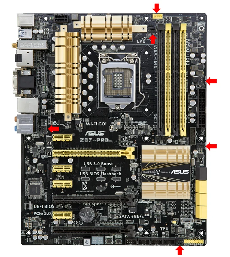
The Z87-Pro features a total of six fan headers, each capable of supplying 1 ampere of current – more than enough for case-fans or other aftermarket solutions.
The other on-board fan headers regulate in DC mode only, so whether you’re using a 4-pin or 3-pin fan, it will be controlled in DC mode, allowing for speed control.
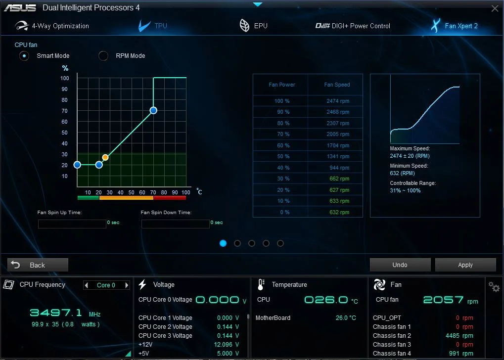
By default, each of the fan headers is setup with a fan control profile. The default profile is labelled “standard” in UEFI, and provides a good speed curve for most fans. There are other profiles and manual parameters that the user can select (more on those later). Or there’s the option to run Fan Xpert 2 via Ai Suite to calibrate the fan speed according to system temperatures.
Once calibration is complete, a profile will be saved and applied automatically. Manual offsets to the fan speed “curve” of each connected fan are also possible if you’d like to change the speed of the fan at a given system temperature. It’s a comprehensive software solution that provides the easiest way to setup a PC with an optimized cooling profile. When temperatures are low, the fans will spin at a slow speed, increasing gradually if temperature rises – keeping noise levels low as possible.
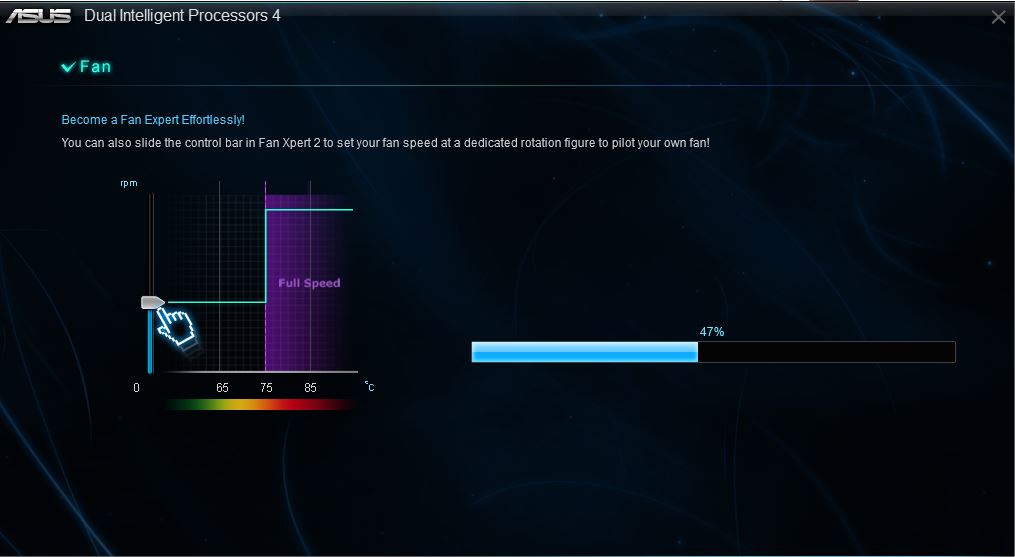
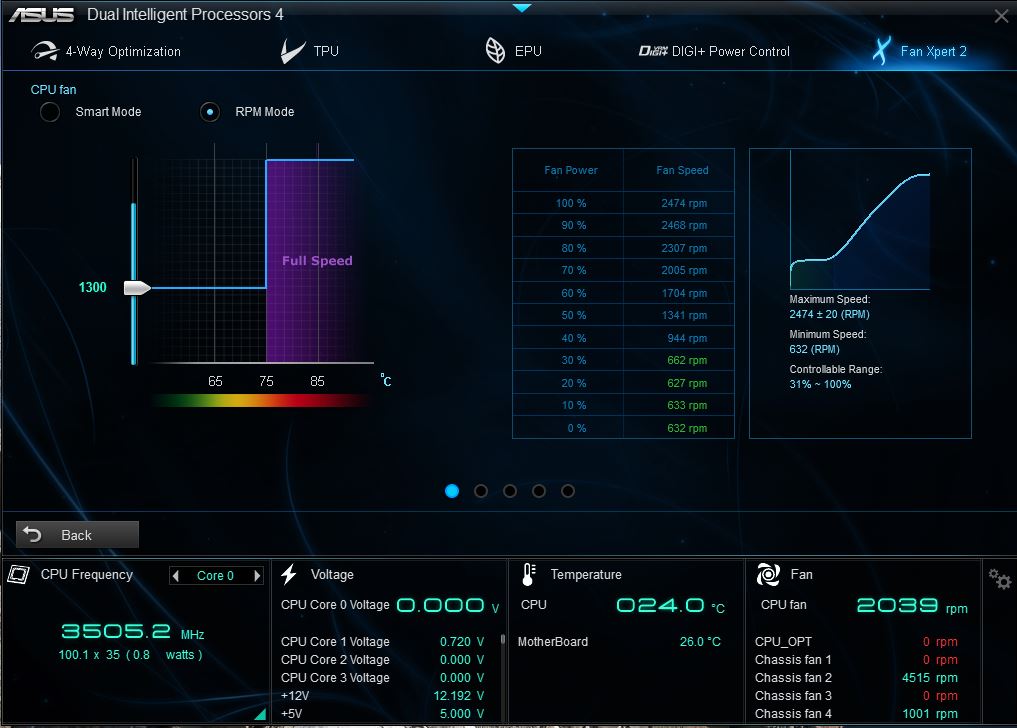
It is also possible to set a static speed for a fan if you wish to do so:
Ai Charger & USB Charger+
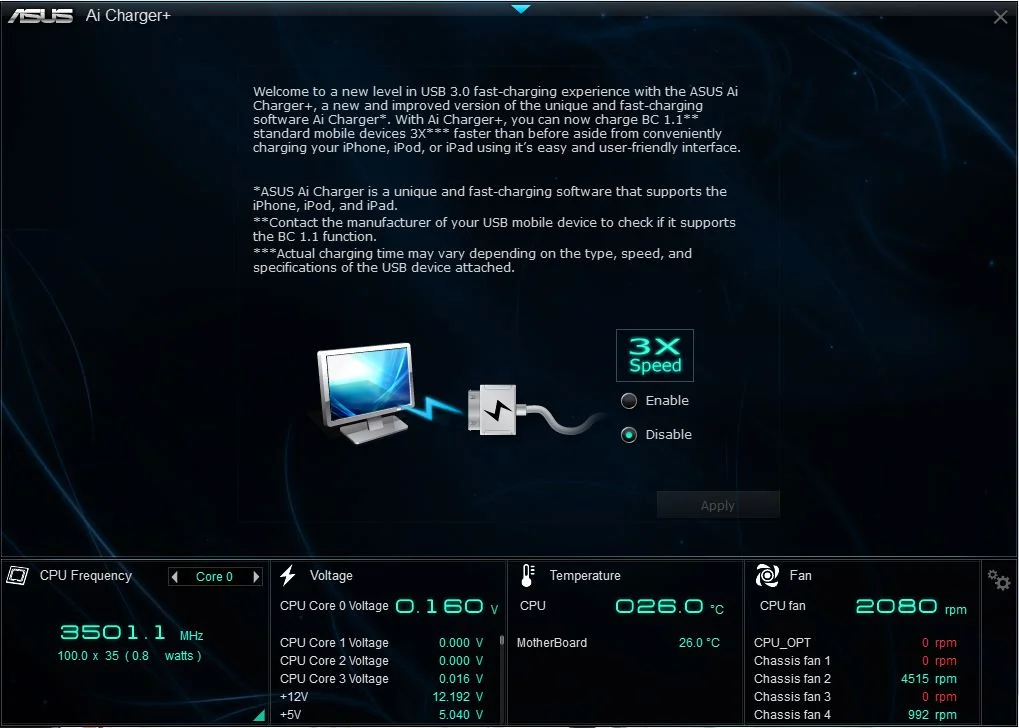
Common usage of mobile devices such as phones and tablets with PCs has led to the need for fast charging support on motherboards. Ordinarily, when a USB 2.0 based device is plugged in, a maximum of 500ma (less for charging) of current is available to use. This makes charging from a motherboard slow in comparison to using the phone or tablet’s own charger. AI Charger and USB Charger+ allow up to 1.2 amps of current to be supplied via the USB ports, facilitating fast-charging of the device.
AI charger is for Apple products, while USB Charger+ supports any BC 1.1 (or later) capable device. Most new phones and tablets are BC 1.1 specification compliant. Once installed, AI Charger or USB Charger + can be used with your compliant device by simply plugging the device into the fast charging port and clicking on the fast charging icon within the respective software interface.
UEFI Features
Unified Extensible Firmware Interface (UEFI) is a software interface between the motherboard firmware and the operating system. The motherboard firmware contains code used to initialize and then program components with parameters.
The UEFI provides a graphical interface that is accessible at system start-up to configure various features and settings available on the motherboard. Attached drives, fans, USB devices, processor power features, overclocking, the system date and time are just a few of the features that users need to access to configure a PC.
While EFI is a defined standard, how a motherboard vendor chooses to represent firmware and platform features graphically to end-users is left to their own ingenuity. The ASUS approach is that the UEFI GUI needs to be intuitive and easy to use. While fancy graphics and colors are a neat touch, an interface that is slow to react to user-commands and has glitches is not acceptable. It is a matter of getting the balance between graphics and usability right. Since UEFI based platforms launched a few years ago, ASUS’s UEFI implementation has become known for offering the smoothest user experience. With each platform release, we aim to develop this further by incorporating new features to enhance performance and functionality of the UEFI.
EZ Mode
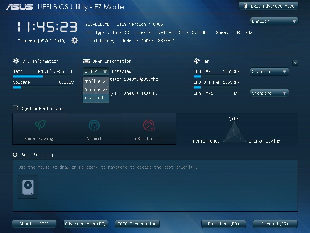
ASUS designed UEFI EZ mode for users that want a simple interface without complications. We’ve added the ability to set the time/date, XMP memory options and select fan profiles directly from EZ-Mode instead of needing to enter the advanced mode to do so. While these are not massive changes, they make setting the system up easier than ever:
Advanced Mode
Switching to advanced mode reveals a number of intuitive new features that both powerusers, as well as occasional tweakers can take advantage of.
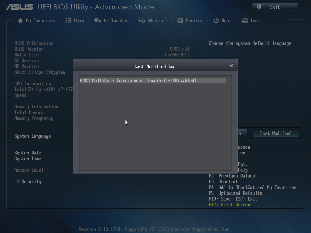
The Last Modified Log keeps a record of the previous changes to UEFI. This is extremely helpful for tracking any unsuccessful changes to the system if a lot of things changed at once.
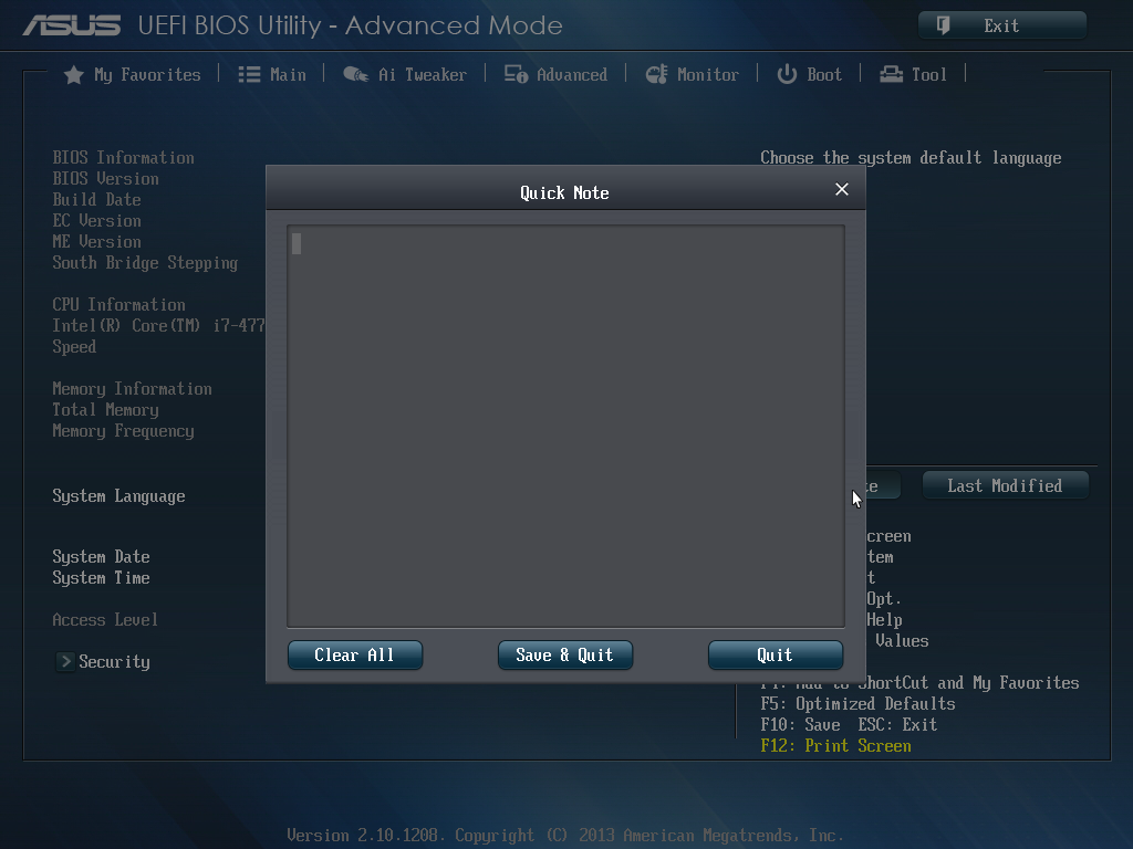
Quick Note is an e-diary that allows user notes of parameter changes to the UEFI settings or for tracking standard text to reference at a later time.
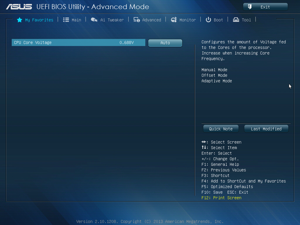
The My Favorites page: allows any function setting in the UEFI to be added to the My Favorites page for convenience. The whole page can be populated with settings from different areas of UEFI, saving time when tuning a system.
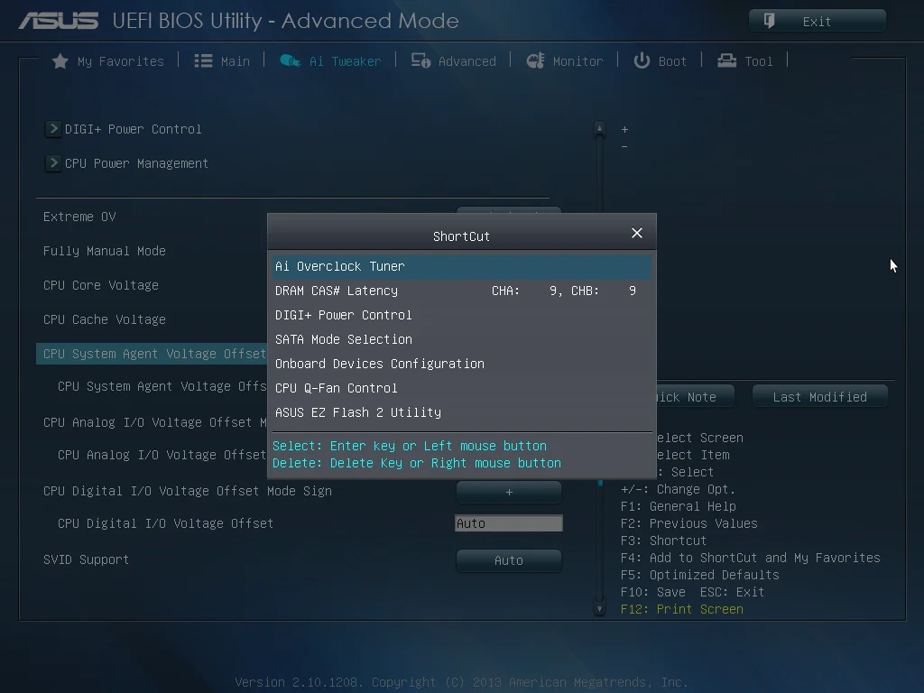
Adding a setting to the Shortcut menu is another way of making UEFI customizable. Right-click on any parameter to add it to the shortcuts list. Choosing a shortcut function in the menu takes the user directly to the selected UEFI setting, which makes navigation simpler and more efficient.
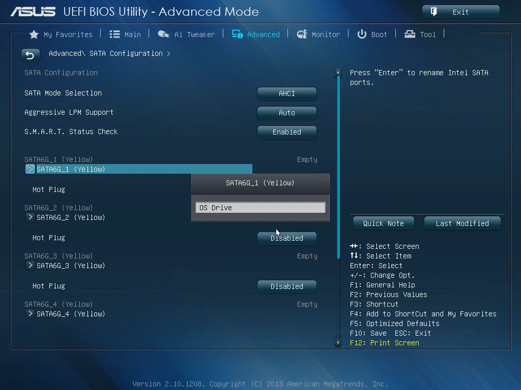
Last but not least is the option to rename each of the SATA ports. When running multiple drives (especially the same model), it can be confusing to know which drive contains the OS or data. Simply rename the ports to indicate what each drive stores to avoid confusion in case it needs removal.
USB BIOS Flashback
ASUS provides three ways to update the UEFI. EZ Flash 2 is accessible via UEFI itself and works independently of the operating system to flash UEFI. EZ Update is a module of AI Suite 3 that downloads the latest UEFI build over the internet and updates it from the operating system. Also included is ASUS’ exclusive USB BIOS Flashback that safely and quickly updates the UEFI. It requires a FAT16 or FAT32 formatted flash drive for the Flashback procedure.
The beauty of USB BIOS flashback is that it can work with standby power – an installed CPU, GPU and memory are not required, and the system does not need to be powered on as with normal firmware updating methods. While power on updating is sufficient in most scenarios, if the system is unstable or loses power the EPROM image required for the board to POST can become corrupt. With USB BIOS flashback, this is not the case. The EPROM section that stores the USB BIOS flashback filename can not be deleted. The board does not require a system POST for USB BIOS flashback to work so the process can re-start after standby power is restored.
Simply insert the USB flash drive in the designated USB port and press the update button for 3 seconds. The LED within the button will then start flashing, and once it stops the flash has completed.
ASUS Z87-Pro Build Video
With the motherboard overview out of the way, we can head over to this video by JJ showing how to build a PC using the ASUS Z87-Pro. There’s valuable additional information about the Z87-Pro in the video, so check it out before building a new Haswell based PC.
[youtube=http://www.youtube.com/watch?v=cUzdNcZeM-s&w=780&rel=0]

