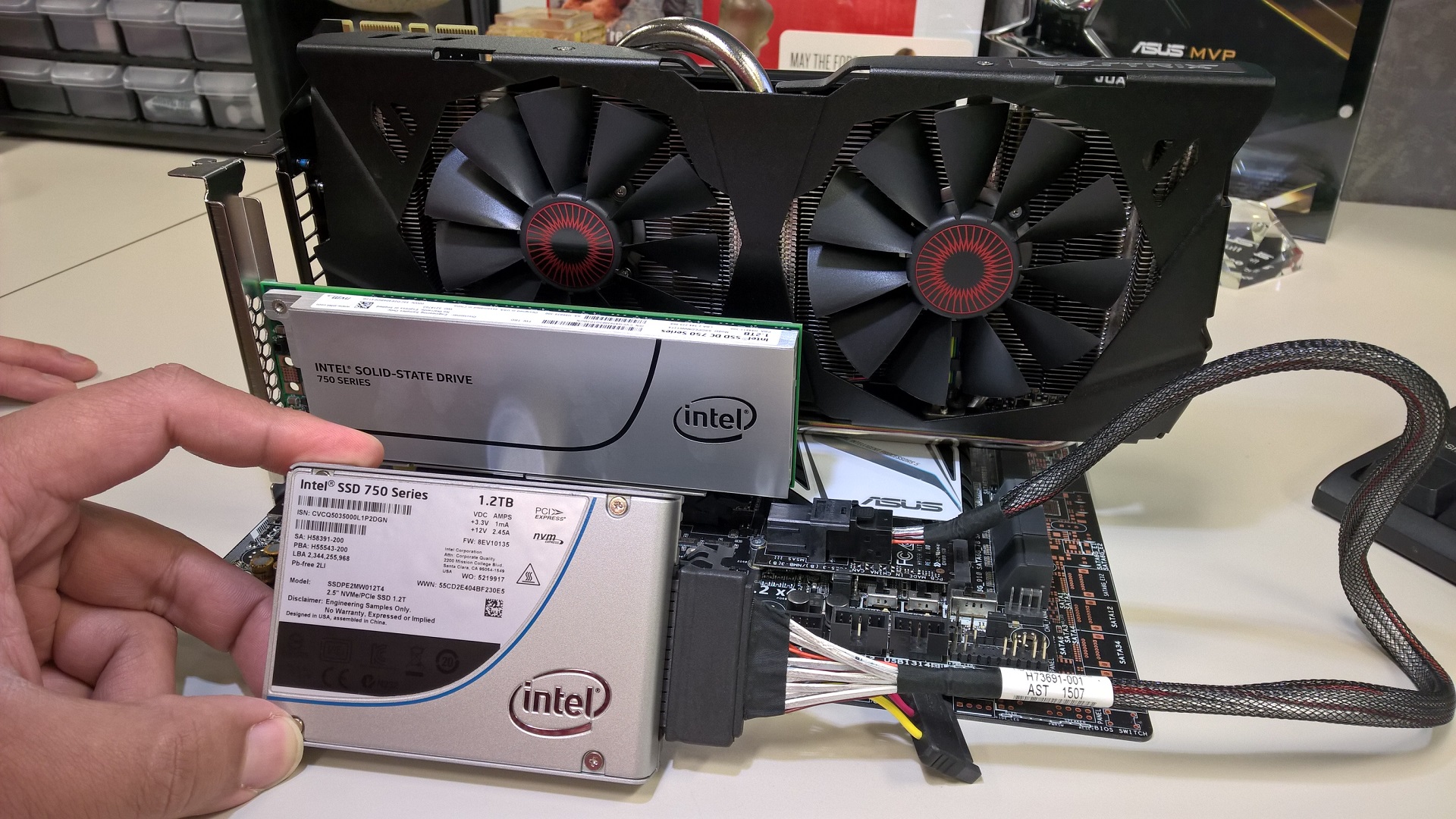
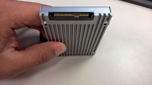
Intel has recently set out to revolutionize the storage world with the release of its latest SDD series, the 750 series. These SSDs are game changers as they bring a consumer based NVMe SSD design replacing legacy AHCI based designs offering up improved performance in IOPS and reads & writes, reduced latency and much more. As always though cutting edge tech has its requirements in ensuring optimal interoperability, compatibility and performance. In this post I am going to give you all the details in helping you feel confident in paring one of Intel’s latest 750 series with ASUS motherboards.
The 750 series of SSDs offer up a wide range of features and functions and performance benefits making them a PC enthusiast, PC gamer or content creator’s best choice for those looking in the best in storage performance. A quick recap of what the 750 series brings to the table and it is easy to see why so many users are excited about these SSDs.
- Enterprise grade Intel SSD controller with 18 channels of flash native NVMe design
- PCIe Gen 3 x4 interface for massive sequential read and write performance
- Consistently higher IOPS and overall throughput
- Extremely fast desktop user queue performance
- Sustained low latency
- Enhanced power loss protection
- Performance consistently not requiring over provision
- Native UEFI firmware offering full support for GOP / GPT windows Installations
- Intel quality firmware and validation with support Intel SSD Toolbox
- Endurance rating – 70GB Writes per day up to 219 TBW ( terabytes written )
- 5 Year warranty
So all of that is great but how do I make sure everything works? Well ASUS and Intel have you covered. A huge amount of work has been put into the interoperability, compatibility and overall performance validation. Overall installation, initialization and usage of the 750 series SSD is essentially the same as any current SSD like the Intel 730 AHCI based SSD. So what do you need to know?
What do I need to run / support an Intel 750 series SSD?
The checklist below is required to ensure optimal functionality and performance
- ASUS X99 or *z97 series motherboard
Models include ( this includes all USB 3.1 variants as well as variants of the Z97-PRO and Z97-DELUXE )
[qd_table]
| Z97 | X99 |
|---|---|
| Z97-AZ97-ARZ97-PROZ97-DELUXE
SABERTOOTH Z97 MARK 1 SABERTOOTH Z97 MARK 2 SABERTOOTH Z97 MARK S GRYPHON Z97 MAXIMUS VII RANGER MAXIMUS VII HERO MAXIMUS VII FORMULA MAXIMUS VII GENE MAXIMUS VII IMPACT Z97-WS |
X99-AX99-PROX99-DELUXESABERTOOTH X99
X99-E WS RAMPAGE V EXTREME |
[/qd_table]
- UEFI compatible hardware ( including a UEFI GOP supported graphics card and optical drive )
All current ASUS graphics cards both AMD and NVIDIA fully support GOP VBIOS previous. Should you have a GTX 600 series GPU or AMD 7000 series GPU you will need to update the VBIOS to be compliant
- NVMe driver – Traditionally a SSD does not need a driver although it is recommended to install the chipset and storage drivers to ensure optimal performance and functionality. Similarly NMVe based SSDs require a driver to ensure the best performance and functionality. Windows does supply a “inbox” driver but it is not recommended. Two ways you will be able to verify the driver is installed is via benchmarking to test the drives performance. Without the NVMe driver maximum sequential throughput will be limited. Additionally you can verify by checking the add / remove programs listing in Windows.
Beyond those items no other requirements.
Important points to be aware of for Intel PCIe AIC ( add in card ) 750 series SSD
For the Intel PCIe AIC ( add in card ) this card requires a UEFI updated which contains the support for enabling a fully bootable NVMe storage solution. All that is required on supported motherboards is updating ( flashing ) the UEFI / BIOS to the updated UEFI.
You can find the UEFI at support.asus.com
Beyond that while the Intel 750 series SSD will operate in any x4 PCIe slot you want to ENSURE that a PCIe Gen 3 slot is utilized. THIS IS THE ONLY WAY TO ENSURE THE SSD’s FULL PERFORMANCE. If a PCIe slot is used that is not PCIe Gen 3 you will still benefit from a wide range of the architectural and performance benefits but you will have considerably limited the maximum sequential performance of the SSD.
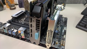
As such it is recommend you use the secondary psychical x16 slot on a motherboard. For both X99 or Z97 this will ensure you can have the drive operate at full bandwidth. These PCIe slots are wired to PCIe lanes from the CPU to support SLI and CROSSFIRE PCIe Gen 3.0 operation.
Important points to be aware of 2.5 M.2 / Hyperkit based Intel 750 series SSD
For the Intel 2.5 M.2 / Hyperkit version of the Intel 750 series SSD it requires a UEFI update which contains the support for enabling a fully bootable NVMe storage solution. All that is required on the noted motherboard is updating ( flashing ) the UEFI / BIOS to the updated UEFI.
THERE ARE IMPORTANT PHYSICAL AND PERFORMANCE CONSIDERATIONS FOR THIS SSD.
Beyond that there is a configuration parameter that ideally must be enabled within the UEFI. This helps to ensure the motherboard recognizes the M.2 Hyperkit SSD as a fully bootable solution.
The Intel 750 series SSD needs a M.2 slot that has been connected to CPU PCIe lanes with a support PCIe lane connection up to 4x ( x4 PCIe ) to ensure it reaches its fully defined performance levels. The Z97 chipset due to a reduced number of PCIe lanes provided by the CPU is not traditionally equipped with M.2 slots offering this level of PCIe connectivity / bandwidth.
This means if installed on a Z97 motherboard the SSD will work and you will still benefit from a wide range of the architecture and performance benefits but you will have considerably limited the maximum sequential performance of the SSD.
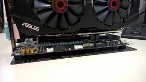
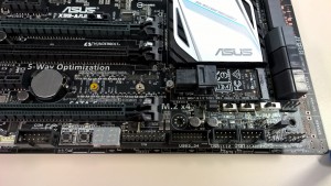
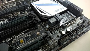
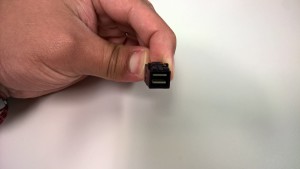
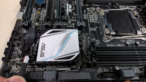
Beyond performance considerations there are mechanical conflict considerations. Due to the height of the SFF-8643 connector on the Hyperkit it can interfere / obstruct graphics cards that run across the M.2 slot. This only an issue for the RAMPAGE V EXTREME and does have a workaround. This issue presents itself if you chose to have a single GPU which extends beyond 9″ inches in the top primary ( 1st ) physical x16 PCIe slot. If you move the card down it eliminates the issue. Other board will experience similar issues in dual GPU configurations. More information is noted below in those cases.
Recommend X99 motherboards for single ( 1 ) GPU setups
SABERTOOTH X99
X99-A
X99-PRO
X99-DELUXE
X99-E WS
Rampage V EXTREME* will work but requires you to move the primary graphics card from the top ( 1st ) physical x16 PCIe slot so it will not be impacted with the Hyperkit.
What about SLI or CROSSFIRE?
For dual GPU configuration only the X99 platform is recommended. This is due to the number of PCIe lanes that the CPU offers enabling support for both dual GPU configurations and full performance of the Intel 750 series SSD.
For X99 motherboards sufficient PCIe lanes are present to support the AIC version of the Intel 750 series SSD. For the 2.5 M.2 / Hyperkit version sufficient lanes are also present but mechanical considerations must be factored. For many X99 motherboards the location of the M.2 slot in combination of the height of the Hyperkit will impact the base of a secondary graphics card causing a mechanical installation conflict.
As such please check clearance prior. Water cooled GPUs present less issues as they are single slot in nature.
Recommended X99 motherboards for SLI or CROSSFIRE
X99-DELUXE
X99-WS
A secondary option for those building a system can use small form factor graphics cards that will offer clearance or not impact with the increased height of the Hyperkit. These cards include
ASUS STRIX GTX 960
ASUS GTX 970 DirectCU Mini
ASUS GTX 960 DirectCU Mini
When using these GPUs board supporting SLI expanded to the
X99-A
X99-PRO
X99-DELUXE
X99-E WS
SABERTOOTH X79
RAMPAGE V EXTREME
What about older chipsets, I have a Z77,Z87, X79 motherboard?
At this time NVMe based storage solutions have not been internally validated and supported via updated firmware. We are currently evaluating bandwidth and resource commit in enabling support on this older chipsets / platforms. Subscribe to PCDIY for updates.
Performance analysis & Benchmarks
Due to the nature of NVMe traditional HD / SSD AHCI based benchmarks especially those designed to demonstrate sequential performance will not correctly show the performance offered by your Intel 750 series SSD. To correctly benchmark the SSD you will need to use
Recommend synthetic benchmark applications
i/o meter
CrystalDisk ( updated version ) designed for NVMe
FAQ
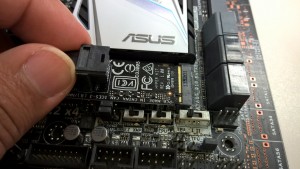
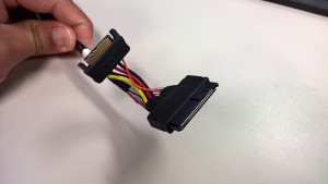
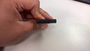
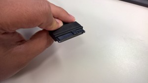
What does the Hyperkit look like?
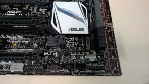
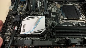
What does a M.2 slot look like?
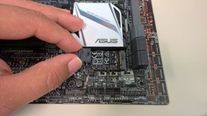
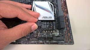
How does it the M.2 slot look like with the Hyperkit installed?
Physical installation guides – Step by step
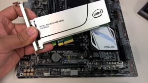
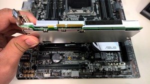
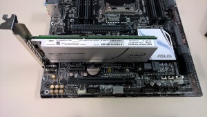
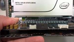
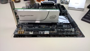
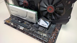
Step by step installation of Intel 750 series SSD AIC ( add in card )
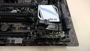
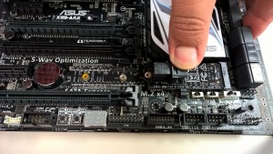
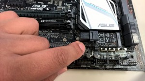
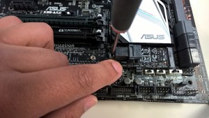
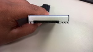
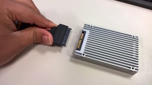
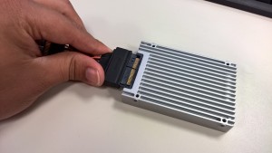
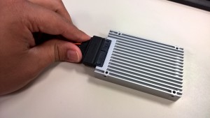
Step by step installation of Intel 750 series 2.5 M.2 / Hyperkit
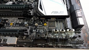
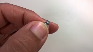


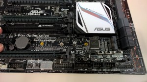


How to enable the Hyperkit within the ASUS UEFI / BIOS:
update coming soon….
How to correctly setup you UEFI for optimal POST & BOOT speed and correctly setting up a UEFI / GPT / GOP system:
update coming soon….

