ASUS UEFI breakdown – Ai Tweaker (cont.)
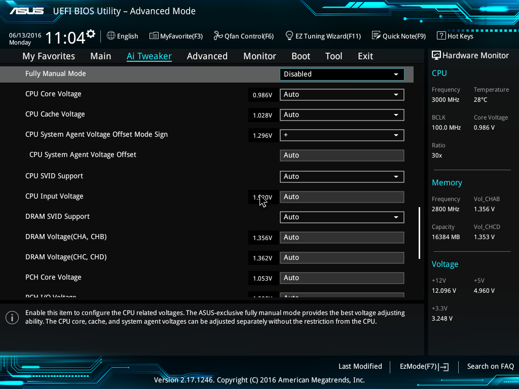
Fully Manual Mode: When disabled, control over internal voltage rails follows Intel’s default policies. When enabled, higher voltage levels are available, and the System Agent voltage can be configured in manual mode as opposed to using offsets.
CPU Core Voltage: Sets the voltage control mode for CPU Vcore:
Manual Mode: Allows setting of a single value for Vcore that is applied across all Core ratios, irrespective of application load.
Offset Mode: In Offset Mode, we can add or subtract voltage from the CPU’s default voltage for a given CPU core ratio. The default voltage scales according to the active multiplier ratio. This provides power saving when application loading is light. The side effect to using offset mode is that any offset value we select will be applied to all core ratios. This can result in too much or too little voltage for a given ratio, which leads to instability.
If you wish to use Offset Mode, then bear in mind that the Vcore displayed in the UEFI is simply a snapshot of the offset voltage stack; the firmware interface only places a partial load on the CPU. The full-load voltage in the operating system will be different, so you will need to check the voltage by running a suitable application within the OS. Use Ai Suite to check the full-load voltage. Also, bear in mind that the default voltage receiving the offset changes with the applied CPU ratio.
Adaptive Mode: Adaptive Mode was developed to account for the inadequacies of Offset Mode for overclocking. We use it to specify the voltage used when the CPU is faced with a heavy application load. The voltage we set is the maximum voltage the PCU is allowed to apply, which takes all the load-related guesswork hampering Offset mode out of the equation. The other boon of Adaptive Mode is that it does not alter voltages for non-Turbo CPU ratios, allowing us to enjoy the benefits of power saving without the voltage adjustment range issues presented by the Offset Mode function. We recommend Adaptive Mode for all normal overclocking.

To use Adaptive Mode, simply enter the full load voltage you wish to use in the Additional Turbo Mode CPU Core Voltage box. So, if you wish to set 1.20V for full load, just type 1.20 into the box. The target full-load voltage is shown in the Total Adaptive Mode CPU Core Voltage area.
Note that the Adaptive voltage target works on the Turbo ratios only. So, if you change the CPU strap and use a non-Turbo CPU ratio, the value in the Adaptive voltage setting box will not be applied. That’s why there is the option to apply an offset when in Adaptive mode. The offset value is added or subtracted from the Additional Turbo Mode CPU Core Voltage box, and the total is displayed in the Total Adaptive Mode CPU Core Voltage pane. The side effect of applying an offset is that it affects the entire voltage stack – from idle to Turbo ratios, which can limit the usable offset voltage range.
CPU Cache Voltage: This sets the voltage for the Uncore and has the same voltage modes available as CPU Core Voltage. However, if you wish to make adjustments to the CPU Cache Voltage, we recommend using Manual or Offset Modes, as the Adaptive Voltage for Uncore does not work correctly for overclocking. This issue exists within the Intel microcode.
CPU System Agent: The System Agent is responsible for handling IO between the CPU and other domains. From an overclocking perspective, the System Agent voltage is especially important for memory overclocking. By default, can only be changed by an offset. To obtain access to Manual Mode, the Fully Manual Mode option must be set to Enabled.
For memory speeds over DDR4-3000 or if using high-density memory kits, voltages up to 1.30V may be required. Some CPUs have “weak” memory controllers that require elevated voltages to maintain stability. If possible, do not venture too far from 1.30V as a maximum.
The System Agent voltage can induce instability if set too high, so it is wise to make gradual changes rather than applying arbitrary values and hoping for the best.
CPU SVID Support: When enabled, this allows communication between the CPU’s PCU (power control unit) and external voltage regulator for VCCIN. It also allows reading of CPU power consumption data by software. The role of SVID from a voltage regulation perspective is to allow communication between the CPU and the onboard voltage regulator (VCCIN regulator) for power saving.
CPU Input Voltage: This provides the 1.80VDC input to the CPU. All primary internal voltage rails are derived and re-regulated from this voltage source. When the CPU is overclocked, this voltage needs to be increased. We recommend keeping the CPU Input Voltage at least 0.45V higher than CPU Vcore, otherwise the system may become unstable or need a higher level of Vcore for stability. The maximum voltage we use is 1.95V set in UEFI. Do note that the actual voltage supplied to the CPU is affected by the LLC setting within the External DIGI+ Power Control menu.
DRAM SVID Support: When enabled, this allows communication between the CPU’s PCU (power control unit) and the onboard DRAM voltage regulators. The role of SVID from a voltage regulation perspective is to allow the CPU to communicate with the onboard DRAM voltage regulator to enable power saving by phase shedding.
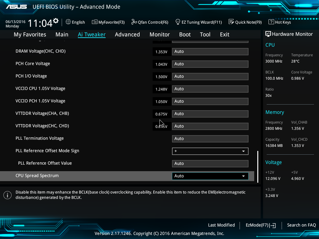
DRAM Voltage (CHA, CHB) & DRAM Voltage (CHA, CHB): Sets the memory voltage (VDIMM) for the memory modules.
PCH Core Voltage: This is the core voltage supply for the PCH (platform controller hub). This setting should not need adjustment for most overclocking.
PCH I/O Voltage: Sets the IO (input/output) voltage for the PCH transceivers that send and receive data to and from the CPU. It should not need adjustment unless the DMI bus is overclocked.
VCCIO CPU 1.05V Voltage: This rail is for the IO transceivers within the CPU. Its primary impact is on memory stability, though it usually does not need to be increased as much as the System Agent voltage. Setting this rail ~0.05V lower than the System Agent Voltage is often sufficient to stabilize memory frequency.
VCCIO PCH 1.05V Voltage: Sets the IO voltage for the CPU transceivers that send and receive data to and from the PCH. It should not need adjustment unless the DMI bus is overclocked.
VTTDRR: Sets the termination voltage for DRAM. 50% of DRAM Voltage is nominal, and by default, this rail will track changes to DRAM voltage. Usually, best stability is at the 50% mark, so this setting can be left at Auto unless the memory configuration is proving unstable and won’t respond to the adjustment of other voltage rails.
PLL termination/PLL Reference/PLL Reference Offset Value: Leave these at Auto; adjustment of these parameters is only beneficial for extreme overclocking with sub-zero CPU cooling.
CPU Spread Spectrum: Can be left on Auto for overclocking. Setting to enabled may induce instability, as clock modulation can affect data sampling margins.


